Wiring Diagram Of A Bell Controlled By A Relay Circuit . In hotel wiring circuit, the bell can be operate from. The circuit diagram of a relay switch typically includes the following components: A switch, relay and a bell is connected as shown in fig. We will introduce the basic knowledge of relay and. A power source, a control circuit, a coil, a set of. When the switch closes, current is applied to a bell causing it to sound. Bell indicator circuit is also known as hotelling circuit where an electric bell is controlled from more than one locations. The diagram consists of two main parts: Here is the most comprehensive guide you can learn about relay wiring diagrams. The relay logic control works efficiently to perform basic on/off operations by opening or closing the relay contacts but it involves a humongous wiring. The schematic is an illustration of the electrical. In a “ladder” diagram, the two poles of the power source are drawn as vertical rails of a ladder, with horizontal “rungs” showing the switch contacts, relay contacts, relay coils, and final. The schematic and the wiring table.
from www.homemade-circuits.com
The circuit diagram of a relay switch typically includes the following components: In hotel wiring circuit, the bell can be operate from. When the switch closes, current is applied to a bell causing it to sound. A power source, a control circuit, a coil, a set of. A switch, relay and a bell is connected as shown in fig. The schematic is an illustration of the electrical. The schematic and the wiring table. The relay logic control works efficiently to perform basic on/off operations by opening or closing the relay contacts but it involves a humongous wiring. Here is the most comprehensive guide you can learn about relay wiring diagrams. The diagram consists of two main parts:
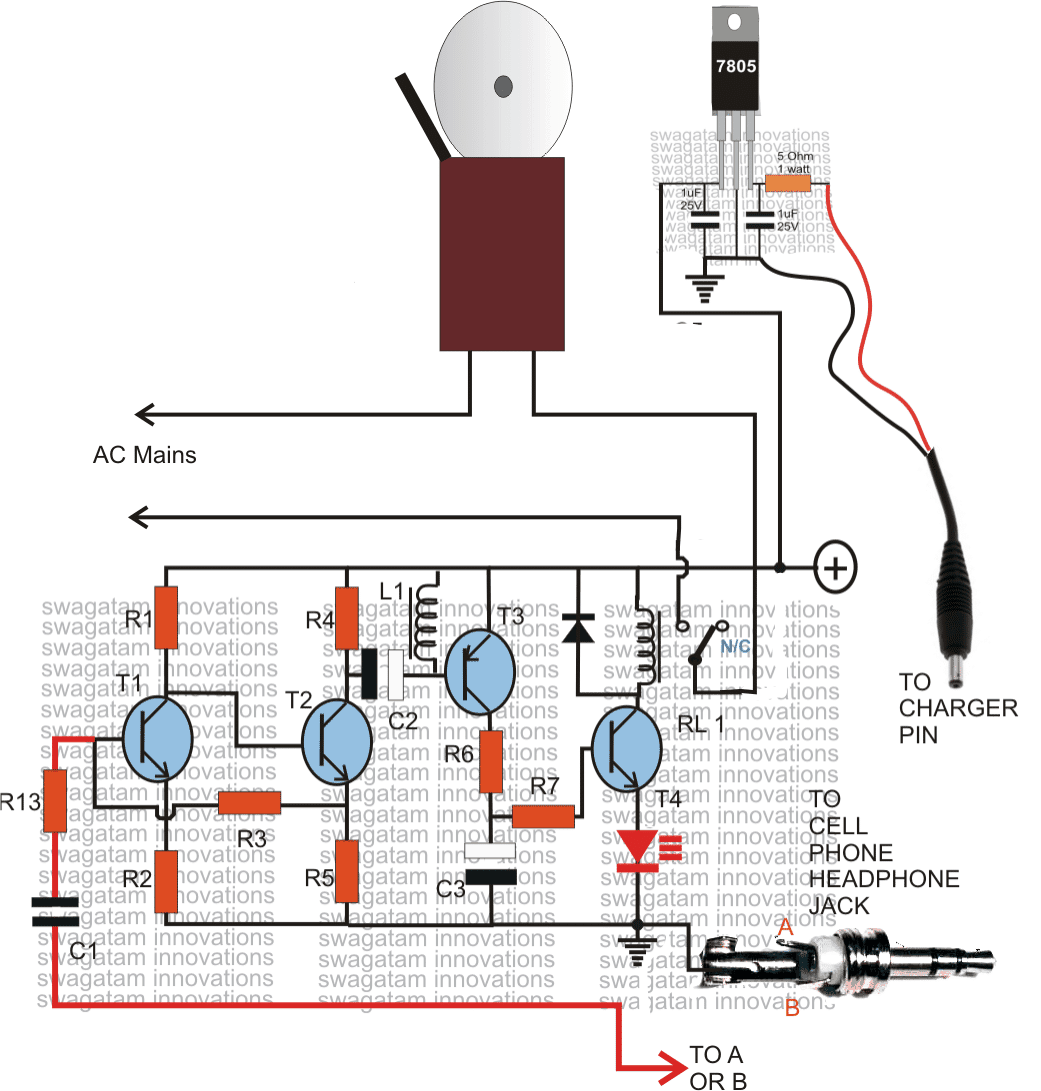
Making a Cell Phone Controlled Remote Bell Circuit Homemade Circuit
Wiring Diagram Of A Bell Controlled By A Relay Circuit A switch, relay and a bell is connected as shown in fig. The schematic and the wiring table. The relay logic control works efficiently to perform basic on/off operations by opening or closing the relay contacts but it involves a humongous wiring. In hotel wiring circuit, the bell can be operate from. The circuit diagram of a relay switch typically includes the following components: A switch, relay and a bell is connected as shown in fig. The diagram consists of two main parts: Bell indicator circuit is also known as hotelling circuit where an electric bell is controlled from more than one locations. Here is the most comprehensive guide you can learn about relay wiring diagrams. We will introduce the basic knowledge of relay and. A power source, a control circuit, a coil, a set of. The schematic is an illustration of the electrical. When the switch closes, current is applied to a bell causing it to sound. In a “ladder” diagram, the two poles of the power source are drawn as vertical rails of a ladder, with horizontal “rungs” showing the switch contacts, relay contacts, relay coils, and final.
From wireparthirsch.z19.web.core.windows.net
Simple Bell Circuit Diagram Wiring Diagram Of A Bell Controlled By A Relay Circuit The relay logic control works efficiently to perform basic on/off operations by opening or closing the relay contacts but it involves a humongous wiring. A power source, a control circuit, a coil, a set of. A switch, relay and a bell is connected as shown in fig. In a “ladder” diagram, the two poles of the power source are drawn. Wiring Diagram Of A Bell Controlled By A Relay Circuit.
From www.wiringview.co
Wiring Diagram 2 Pin Flasher Unit Wiring View and Schematics Diagram Wiring Diagram Of A Bell Controlled By A Relay Circuit Bell indicator circuit is also known as hotelling circuit where an electric bell is controlled from more than one locations. The relay logic control works efficiently to perform basic on/off operations by opening or closing the relay contacts but it involves a humongous wiring. A power source, a control circuit, a coil, a set of. A switch, relay and a. Wiring Diagram Of A Bell Controlled By A Relay Circuit.
From wiringlibrarydelia.z4.web.core.windows.net
Wire Diagram Of Door Bell Installations Wiring Diagram Of A Bell Controlled By A Relay Circuit The schematic is an illustration of the electrical. In a “ladder” diagram, the two poles of the power source are drawn as vertical rails of a ladder, with horizontal “rungs” showing the switch contacts, relay contacts, relay coils, and final. The diagram consists of two main parts: The relay logic control works efficiently to perform basic on/off operations by opening. Wiring Diagram Of A Bell Controlled By A Relay Circuit.
From smart-ion.com
Impulse relays to control lighting and their use Smart ION Wiring Diagram Of A Bell Controlled By A Relay Circuit The diagram consists of two main parts: The schematic is an illustration of the electrical. The circuit diagram of a relay switch typically includes the following components: Here is the most comprehensive guide you can learn about relay wiring diagrams. The schematic and the wiring table. A switch, relay and a bell is connected as shown in fig. In hotel. Wiring Diagram Of A Bell Controlled By A Relay Circuit.
From schematicpartclaudia.z19.web.core.windows.net
Relay Switch Circuit Diagram Wiring Diagram Of A Bell Controlled By A Relay Circuit The diagram consists of two main parts: In hotel wiring circuit, the bell can be operate from. The circuit diagram of a relay switch typically includes the following components: A switch, relay and a bell is connected as shown in fig. The relay logic control works efficiently to perform basic on/off operations by opening or closing the relay contacts but. Wiring Diagram Of A Bell Controlled By A Relay Circuit.
From userfixfrey.z19.web.core.windows.net
Phase Reversal Relay Circuit Diagram Wiring Diagram Of A Bell Controlled By A Relay Circuit A power source, a control circuit, a coil, a set of. The relay logic control works efficiently to perform basic on/off operations by opening or closing the relay contacts but it involves a humongous wiring. In hotel wiring circuit, the bell can be operate from. We will introduce the basic knowledge of relay and. The diagram consists of two main. Wiring Diagram Of A Bell Controlled By A Relay Circuit.
From manuallibfletcher.z19.web.core.windows.net
Bell Circuit Wiring Diagram Wiring Diagram Of A Bell Controlled By A Relay Circuit A switch, relay and a bell is connected as shown in fig. Bell indicator circuit is also known as hotelling circuit where an electric bell is controlled from more than one locations. In hotel wiring circuit, the bell can be operate from. A power source, a control circuit, a coil, a set of. When the switch closes, current is applied. Wiring Diagram Of A Bell Controlled By A Relay Circuit.
From thowpic06.blogspot.com
Schematic Diagram Of Electric Bell Figure 7 Shows A Simple Electric Wiring Diagram Of A Bell Controlled By A Relay Circuit The schematic is an illustration of the electrical. The schematic and the wiring table. Here is the most comprehensive guide you can learn about relay wiring diagrams. A power source, a control circuit, a coil, a set of. In hotel wiring circuit, the bell can be operate from. We will introduce the basic knowledge of relay and. The diagram consists. Wiring Diagram Of A Bell Controlled By A Relay Circuit.
From tronicspro.com
PIR Controlled Shop Bell Circuit Diagram TRONICSpro Wiring Diagram Of A Bell Controlled By A Relay Circuit In a “ladder” diagram, the two poles of the power source are drawn as vertical rails of a ladder, with horizontal “rungs” showing the switch contacts, relay contacts, relay coils, and final. The diagram consists of two main parts: Here is the most comprehensive guide you can learn about relay wiring diagrams. The schematic is an illustration of the electrical.. Wiring Diagram Of A Bell Controlled By A Relay Circuit.
From www.homemade-circuits.com
Making a Cell Phone Controlled Remote Bell Circuit Homemade Circuit Wiring Diagram Of A Bell Controlled By A Relay Circuit The schematic is an illustration of the electrical. A power source, a control circuit, a coil, a set of. The diagram consists of two main parts: The schematic and the wiring table. In a “ladder” diagram, the two poles of the power source are drawn as vertical rails of a ladder, with horizontal “rungs” showing the switch contacts, relay contacts,. Wiring Diagram Of A Bell Controlled By A Relay Circuit.
From www.caretxdigital.com
musical doorbell circuit diagram Wiring Diagram and Schematics Wiring Diagram Of A Bell Controlled By A Relay Circuit The diagram consists of two main parts: The relay logic control works efficiently to perform basic on/off operations by opening or closing the relay contacts but it involves a humongous wiring. Bell indicator circuit is also known as hotelling circuit where an electric bell is controlled from more than one locations. Here is the most comprehensive guide you can learn. Wiring Diagram Of A Bell Controlled By A Relay Circuit.
From www.dreamstime.com
Electric Bell Diagram Showing Use Stock Vector Wiring Diagram Of A Bell Controlled By A Relay Circuit A power source, a control circuit, a coil, a set of. When the switch closes, current is applied to a bell causing it to sound. The schematic and the wiring table. Here is the most comprehensive guide you can learn about relay wiring diagrams. The circuit diagram of a relay switch typically includes the following components: Bell indicator circuit is. Wiring Diagram Of A Bell Controlled By A Relay Circuit.
From www.electricaltechnology.org
Hotel Wiring Circuit Bell Indicator Circuit For Hotelling Wiring Diagram Of A Bell Controlled By A Relay Circuit In hotel wiring circuit, the bell can be operate from. Bell indicator circuit is also known as hotelling circuit where an electric bell is controlled from more than one locations. A power source, a control circuit, a coil, a set of. We will introduce the basic knowledge of relay and. Here is the most comprehensive guide you can learn about. Wiring Diagram Of A Bell Controlled By A Relay Circuit.
From wiringfixsprained.z19.web.core.windows.net
Electric Bell Circuit Diagram Wiring Diagram Of A Bell Controlled By A Relay Circuit The relay logic control works efficiently to perform basic on/off operations by opening or closing the relay contacts but it involves a humongous wiring. A power source, a control circuit, a coil, a set of. In hotel wiring circuit, the bell can be operate from. The diagram consists of two main parts: Bell indicator circuit is also known as hotelling. Wiring Diagram Of A Bell Controlled By A Relay Circuit.
From schematicpillaged.z14.web.core.windows.net
Ring Doorbell Wiring Diagram Cap Wiring Diagram Of A Bell Controlled By A Relay Circuit Here is the most comprehensive guide you can learn about relay wiring diagrams. In a “ladder” diagram, the two poles of the power source are drawn as vertical rails of a ladder, with horizontal “rungs” showing the switch contacts, relay contacts, relay coils, and final. The schematic and the wiring table. We will introduce the basic knowledge of relay and.. Wiring Diagram Of A Bell Controlled By A Relay Circuit.
From circuitenginejeffrey.z21.web.core.windows.net
Simple Electric Bell Circuit Diagram Wiring Diagram Of A Bell Controlled By A Relay Circuit Bell indicator circuit is also known as hotelling circuit where an electric bell is controlled from more than one locations. The relay logic control works efficiently to perform basic on/off operations by opening or closing the relay contacts but it involves a humongous wiring. In hotel wiring circuit, the bell can be operate from. A power source, a control circuit,. Wiring Diagram Of A Bell Controlled By A Relay Circuit.
From www.oceanproperty.co.th
SOLVED Draw A WIRING DIAGRAM For Wiring A Push Button, 54 OFF Wiring Diagram Of A Bell Controlled By A Relay Circuit In a “ladder” diagram, the two poles of the power source are drawn as vertical rails of a ladder, with horizontal “rungs” showing the switch contacts, relay contacts, relay coils, and final. We will introduce the basic knowledge of relay and. The schematic is an illustration of the electrical. When the switch closes, current is applied to a bell causing. Wiring Diagram Of A Bell Controlled By A Relay Circuit.
From circuitpartehrlichmann.z19.web.core.windows.net
Electronic Relay Circuit Diagram Wiring Diagram Of A Bell Controlled By A Relay Circuit The circuit diagram of a relay switch typically includes the following components: Here is the most comprehensive guide you can learn about relay wiring diagrams. The schematic and the wiring table. A power source, a control circuit, a coil, a set of. The schematic is an illustration of the electrical. The relay logic control works efficiently to perform basic on/off. Wiring Diagram Of A Bell Controlled By A Relay Circuit.